Checking Valve Clearance
- Remove cover over intake camshaft. Remove upper timing cover and cover over ignition coils. See Figure.
- Mark location of ignition coils and remove. DO NOT disconnect electrical connectors. Disconnect ground connections and connector for variable valve timing solenoid.
- Raise and support vehicle. Remove right front wheel.
NOTE:
Camshaft Setting Tool MUST be in correct starting position with correct timing belt tension. If crankshaft is turned too far, turn it backward at least one quarter turn and then turn clockwise to correct position.
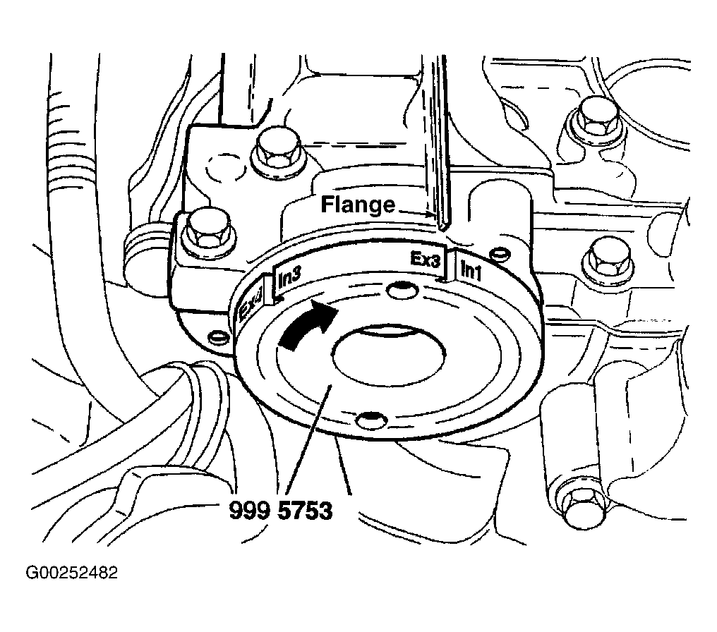
- Install Camshaft Setting Tool (999-5753) at rear of intake camshaft. Turn crankshaft clockwise until marking In1/Ex3 on setting tool is opposite to flange running over entire top of cylinder head. Remove plugs from check holes. See Fig 1.
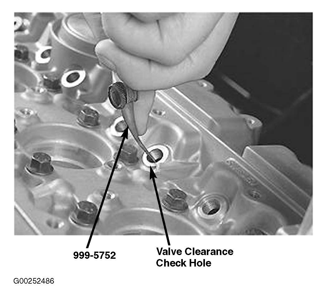
- Use Feeler Gauge (999-5752) or equivalent gauge to check valve clearance at cylinder No. 1 intake valves and cylinder No. 3 exhaust valves. Insert gauge through check holes and bend gauge with light pressure so it follows top of valve lifter. Feeler gauge must be inserted approximately .6" (15 mm) for correct measurement. See Fig 2 and VALVE CLEARANCE SPECIFICATIONS (CHECK)
table for normal valve clearances.
- Turn crankshaft clockwise until marking In2/Ex1 on camshaft setting tool is opposite to flange running over entire top of cylinder head. Repeat check procedure in step 5 for cylinder No. 2 intake valves and cylinder No. 1 exhaust valves. Go to next step.
- Rotate crankshaft clockwise until next marking on camshaft setting tool is opposite to flange running over entire top of cylinder head. Repeat check procedure in step 5 for corresponding intake and exhaust valves. Repeat for all intake and exhaust valves. If any valve clearances are not within specification, See ADJUSTING VALVE CLEARANCE .
- Install check hole plugs when all valves are checked. Install remaining components in reverse order of removal.
VALVE CLEARANCE SPECIFICATIONS (CHECK)
| Application |
Specification - In. (mm) |
| Intake Valves |
.006-.017 (.15-.45) |
| Exhaust Valves |
.014-.024 (.35-.60) |
 Courtesy of VOLVO CARS OF NORTH AMERICA.
 Courtesy of VOLVO CARS OF NORTH AMERICA.