Transaxle Disassembly: Notes
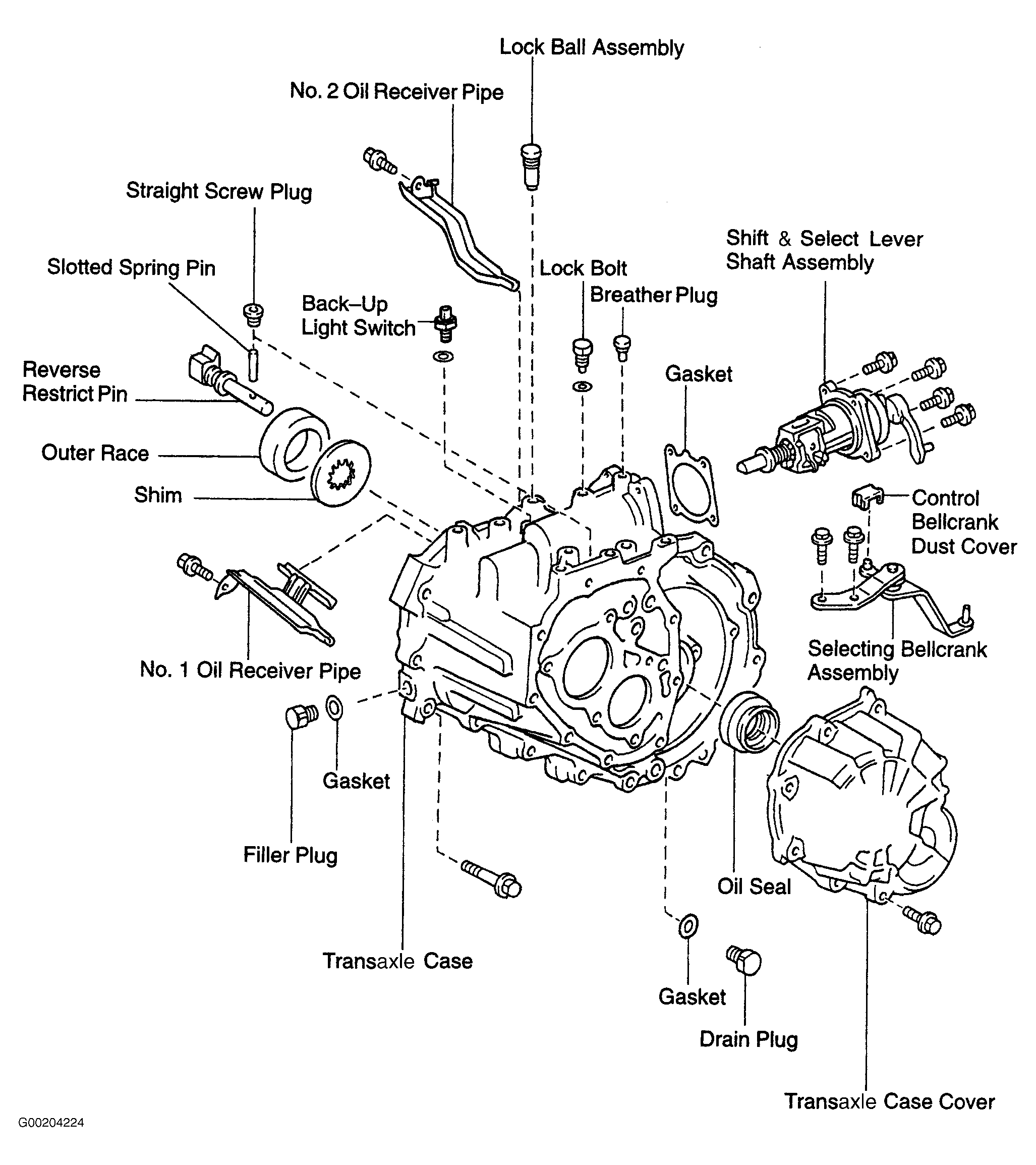
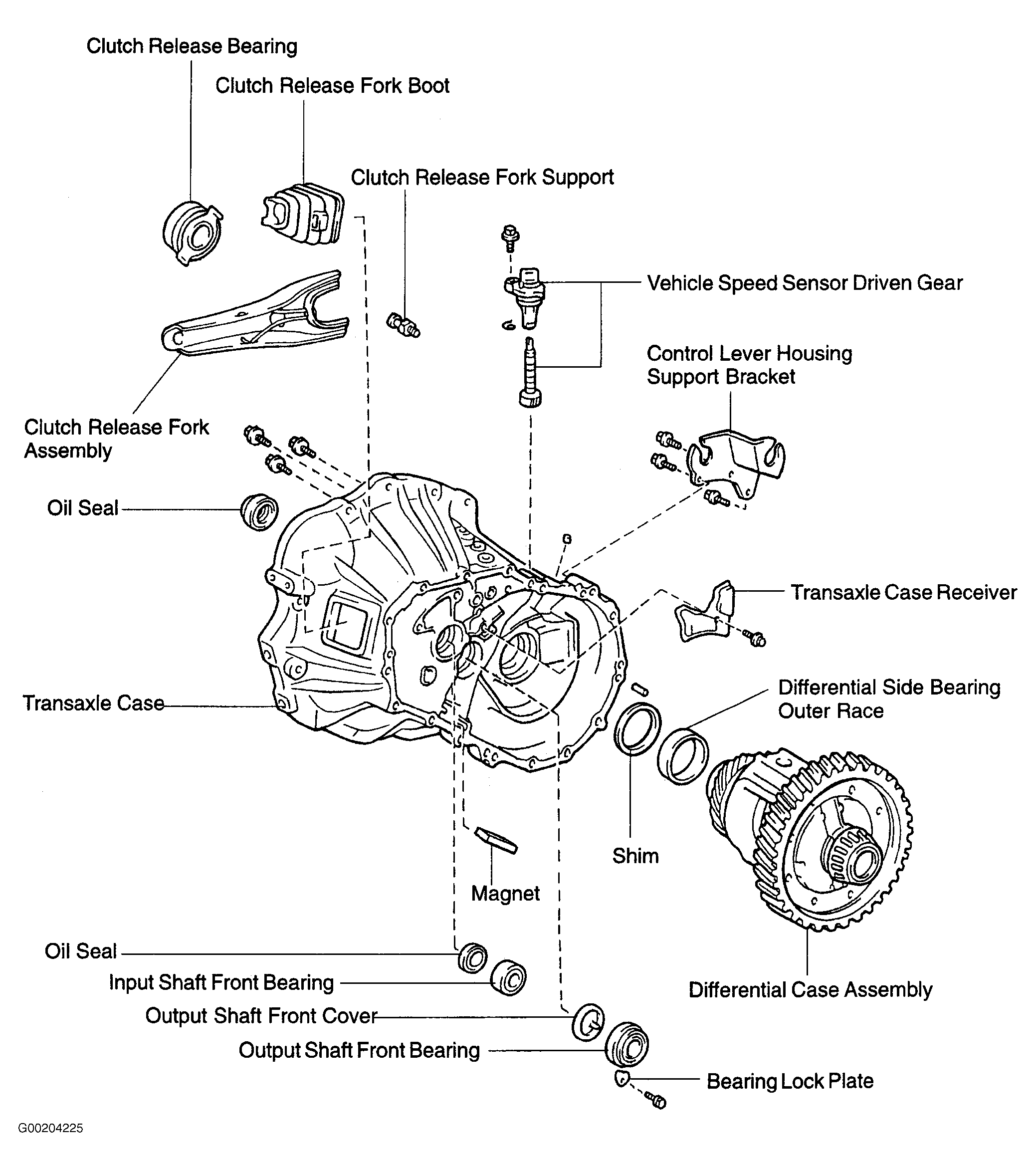
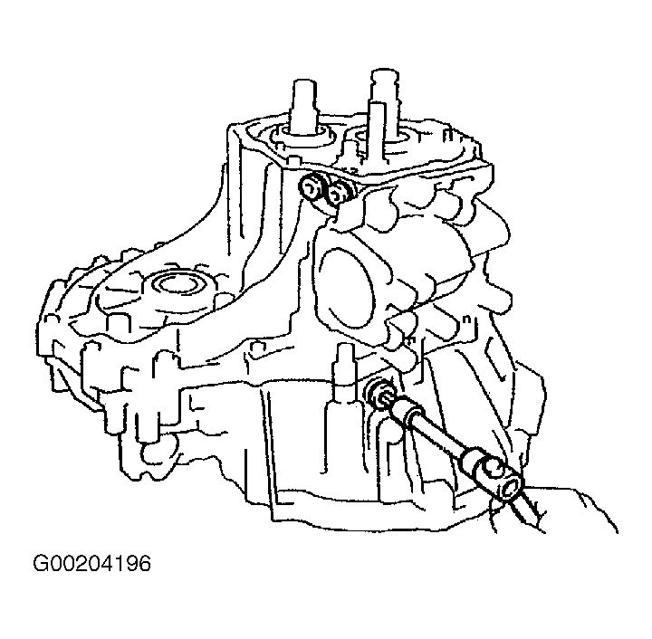
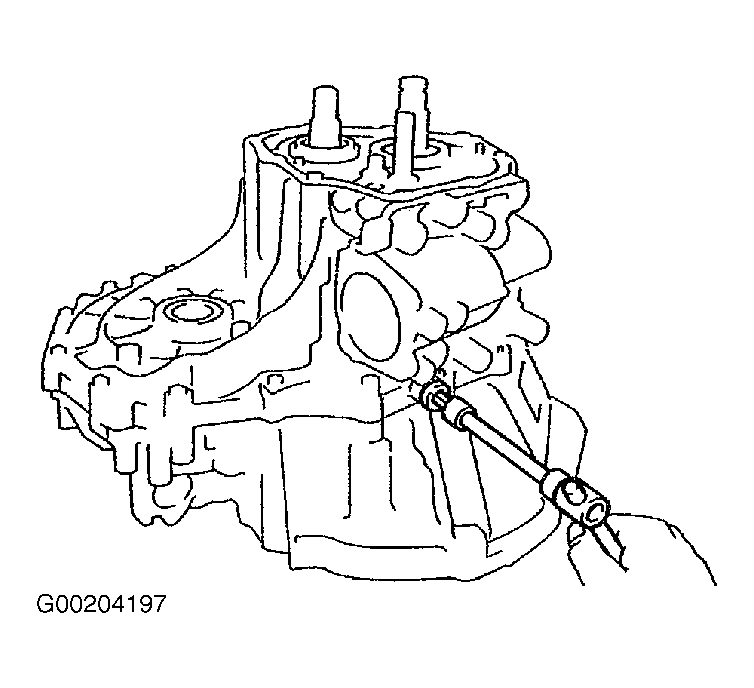
- Remove filler plug and drain plug with 2 gaskets. See Fig 1. Remove release fork assembly and release bearing. Remove release fork boot and release fork support. Remove bolt and vehicle speed sensor driven gear. See Fig 2. Remove back-up light switch. Remove 2 bolts and selecting bellcrank assembly. Remove control bellcrank dust cover from selecting bellcrank assembly. See Fig 1.
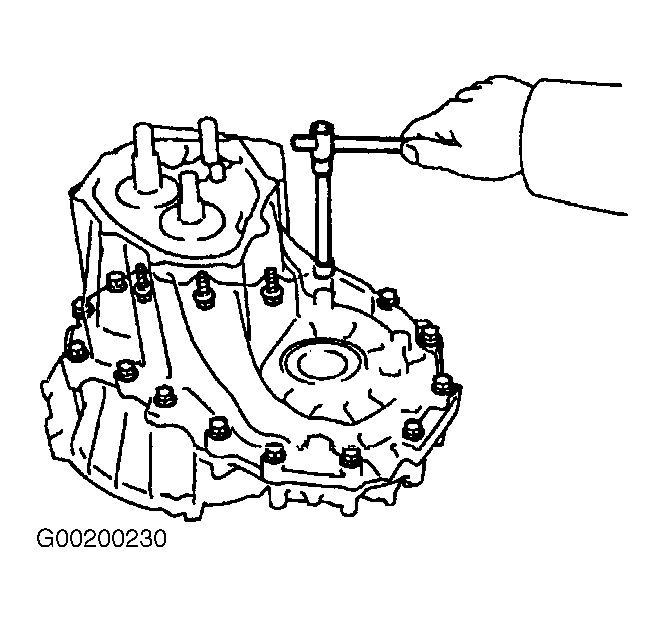
- Remove 3 bolts and control lever housing support bracket. See Fig 2. Remove 9 transaxle case cover bolts. See Figure. Using a brass drift and a hammer, carefully tap projection of transaxle case cover to remove case cover from transaxle case. Remove lock bolt. Remove 4 bolts, and pull out shift and select lever shaft assembly with gasket. See Fig 1.
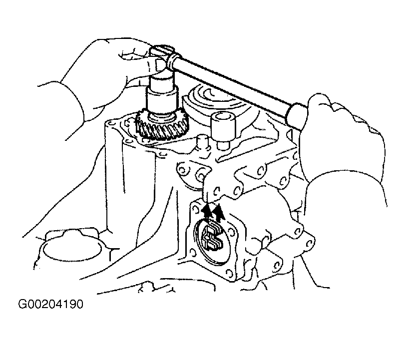
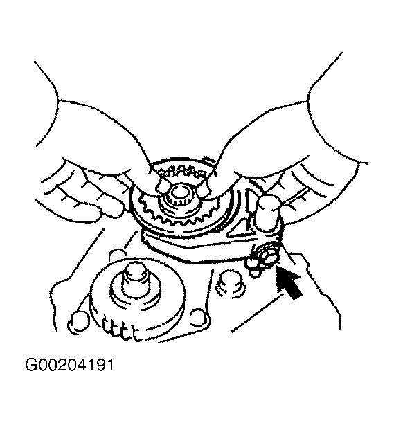
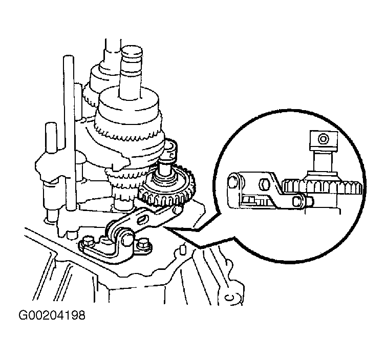
- Engage gear double meshing. Using a chisel and a hammer, loosen staked part of lock nut on output shaft. Remove lock nut. See Fig 3. Disengage gear double meshing. Remove bolt from No. 3 gear shift fork. Remove No. 3 hub sleeve and 3 shifting keys with No. 3 gear shift fork. See Fig 4.
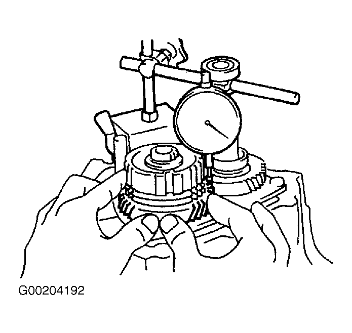
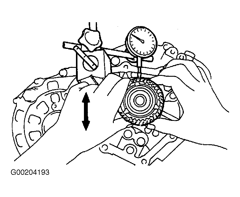
- Using a dial indicator, measure 5th gear thrust clearance. See Fig 5. Standard clearance is .0039-.0224" (.100-.570 mm). Service limit is .0256" (.650 mm). Measure 5th gear radial clearance. See Fig 6. Standard clearance is .0006-.0023 (.015-.058). Service limit is .0028" (.070 mm). If clearances exceed specification, replace gear, needle roller bearing or shaft.
- Using 2 screwdrivers and a hammer, tap out 5th gear snap ring. Using a screwdriver, pry out shifting key spring from No. 3 clutch hub. Install a bolt and washer to the tip of input shaft. Select a bolt with an outer diameter smaller than screw hole of input shaft so that bolt can be turned easily. Using Puller Set (09950-30012), remove No. 3 clutch hub.
- Using a screwdriver, pry out shifting key spring from other side of No. 3 clutch hub. Remove No. 3 synchronizer ring, 5th gear, needle roller bearing and spacer. Using Puller Set (09950-40011), remove 5th driven gear.
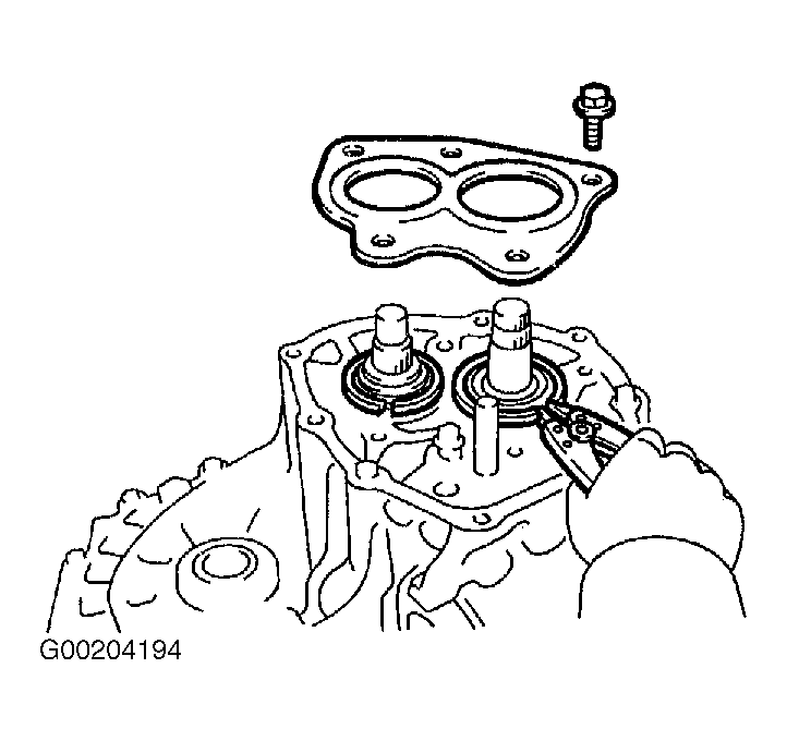
- Remove 5 bolts and rear bearing retainer. See Fig 16. Using snap ring expander, remove 2 snap rings while pulling up on shafts. See Fig 7.
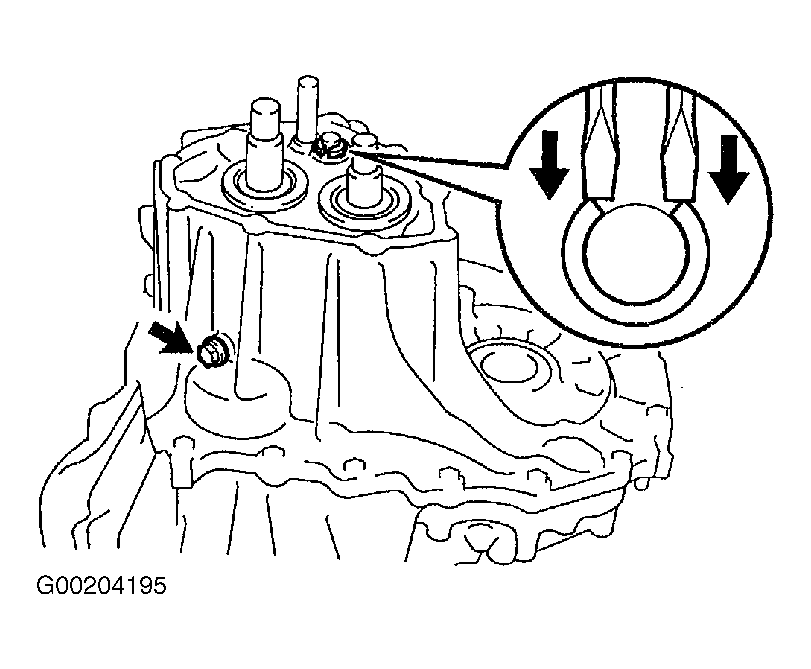
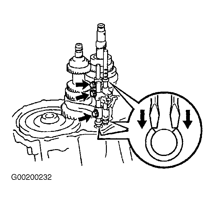
- Remove reverse idler gear shaft lock bolt and gasket. Using 2 screwdrivers and a hammer, remove snap ring from No. 2 shift fork shaft. See Fig 8. Using hexagon wrench, remove 3 straight screw plugs. See Fig 9. Using magnetic finger, remove 3 seats, springs and balls. Using hexagon wrench, remove lock ball assembly. See Fig 10.
- Remove 16 transaxle case bolts. See Fig 11. Using a plastic-faced hammer, carefully tap projection of transaxle case to separate case halves. Remove 2 bolts and oil receiver pipes from transaxle case. See Figure. Remove reverse idler gear, thrust washer and shaft. Remove 2 bolts and reverse shift arm bracket. See Fig 12.
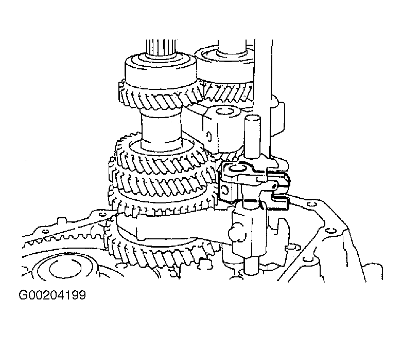
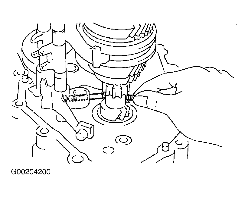
- Using 2 screwdrivers and a hammer, tap out 3 snap rings from each gear shift fork shaft. Remove No. 1 gear shift head, No. 1 and No. 2 gear shift fork set bolts. See Fig 13. Pull up No. 3 gear shift fork shaft, and remove No. 2 gear shift fork shaft. Remove No. 1 gear shift head. See Fig 14. Using magnetic finger, remove 2 balls from reverse shift fork. See Fig 15. Remove No. 3 gear shift fork shaft and reverse shift fork. Pull out No. 1 gear shift fork shaft from transaxle case.
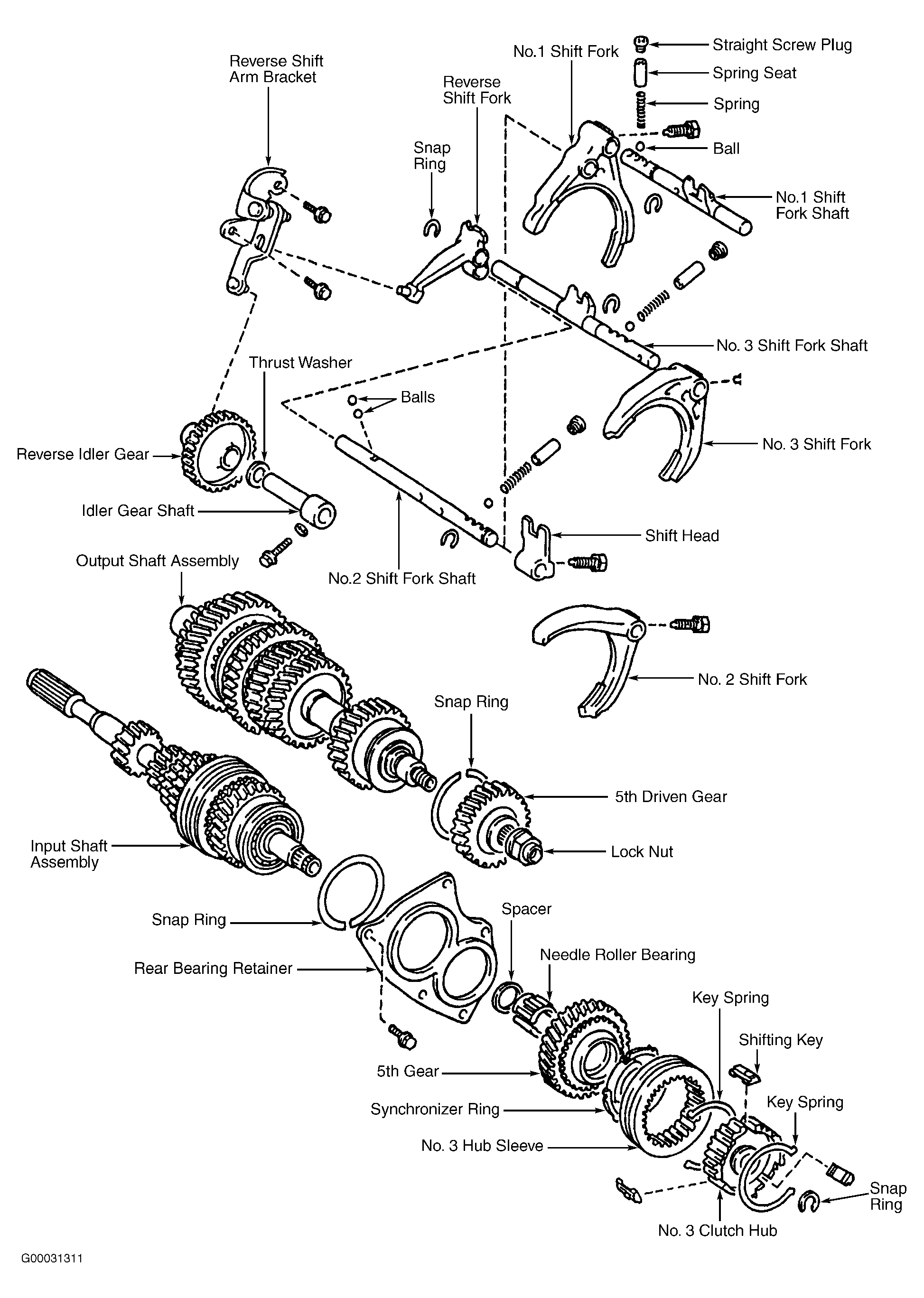
- Remove No. 1 and No. 2 gear shift forks. Remove input and output shafts from transaxle case. Remove differential case assembly. See Fig 2. Remove magnet from transaxle case. Remove bolt and transaxle case receiver from transaxle case. See Fig 2. Using a screwdriver, remove 2 shifting key springs. Remove No. 3 shifting keys (3) from No. 3 clutch hub.
 Courtesy of © TOYOTA, LICENSE AGREEMENT TMS1002
 Courtesy of © TOYOTA, LICENSE AGREEMENT TMS1002
 Courtesy of © TOYOTA, LICENSE AGREEMENT TMS1002
 Courtesy of © TOYOTA, LICENSE AGREEMENT TMS1002
 Courtesy of © TOYOTA, LICENSE AGREEMENT TMS1002
 Courtesy of © TOYOTA, LICENSE AGREEMENT TMS1002
 Courtesy of © TOYOTA, LICENSE AGREEMENT TMS1002
 Courtesy of © TOYOTA, LICENSE AGREEMENT TMS1002
 Courtesy of © TOYOTA, LICENSE AGREEMENT TMS1002
 Courtesy of © TOYOTA, LICENSE AGREEMENT TMS1002
 Courtesy of © TOYOTA, LICENSE AGREEMENT TMS1002
 Courtesy of © TOYOTA, LICENSE AGREEMENT TMS1002
 Courtesy of © TOYOTA, LICENSE AGREEMENT TMS1002
 Courtesy of © TOYOTA, LICENSE AGREEMENT TMS1002
 Courtesy of © TOYOTA, LICENSE AGREEMENT TMS1002
 Courtesy of © TOYOTA, LICENSE AGREEMENT TMS1002