Removal Procedure
- Raise and support the vehicle. Refer to LIFTING AND JACKING THE VEHICLE
in General Information.
- Remove the tire and the wheel. Refer to TIRE AND WHEEL REMOVAL AND INSTALLATION
in Tires and Wheels.
- Support rear differential carrier using utility stand.
- Remove the rear differential carrier mounting bolts (5) from the rear crossmember. Refer to DIFFERENTIAL REPLACEMENT
in Rear Drive Axle.
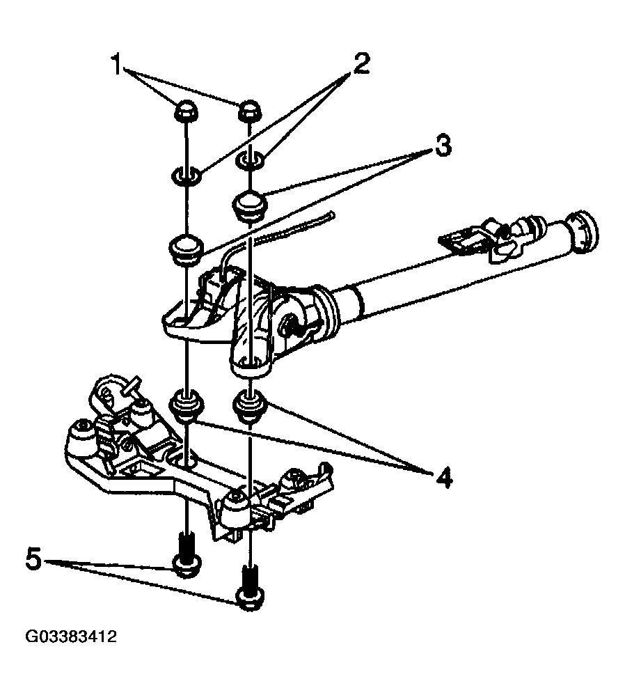 Courtesy of GENERAL MOTORS CORP.
- Remove the rear suspension knuckle. Refer to KNUCKLE REPLACEMENT (ALL WHEEL DRIVE)
in Rear Suspension.
- Disconnect the wheel speed sensor harness from the lower control arm and from the rear cross member.
- Remove the rivets that attach the park brake cable to the rear crossmember.
- Remove the ALC height sensor and link. Refer to AUTOMATIC LEVEL CONTROL SENSOR REPLACEMENT
in Automatic Level Control.
- Remove the ALC ball stud.
- Secure the ALC wiring harness out of the way.
- Using a utility jack, support the rear crossmember.
- Scribe the rear crossmember mounting points to the frame.
- Remove the rear crossmember mounting bolts.
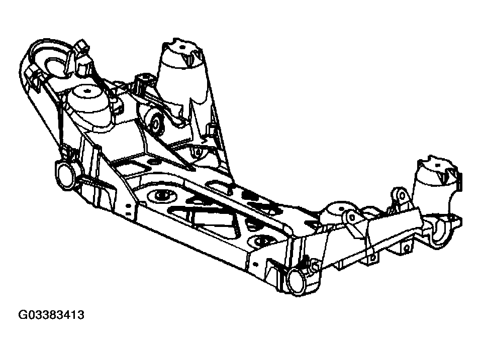 Courtesy of GENERAL MOTORS CORP.
- Lower the rear crossmember.
- Remove the rear stabilizer shaft. Refer to STABILIZER SHAFT REPLACEMENT (ALL WHEEL DRIVE)
in Rear Suspension.
- Remove the rear axle upper control arms from the rear crossmember. Refer to REAR AXLE UPPER CONTROL ARM REPLACEMENT (ALL WHEEL DRIVE)
in Rear Suspension.
- Remove the rear axle lower control arms from the rear crossmember. Refer to REAR AXLE LOWER CONTROL ARM REPLACEMENT (ALL WHEEL DRIVE)
in Rear Suspension.
- Remove the tie rods from the rear crossmember. Refer to TIE ROD REPLACEMENT (FRONT WHEEL DRIVE)
or TIE ROD REPLACEMENT (ALL WHEEL DRIVE)
in Rear Suspension.