Test D: Transmission Range Sensor
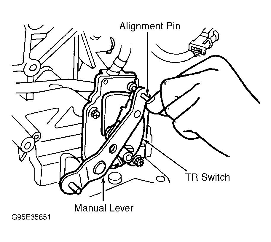
- Ensure TR sensor is properly aligned. See Fig 1
. Adjust as necessary, and then go to next step.
- Inspect TR sensor harness connector for damage or corrosion to terminals. Repair as necessary, and go to next step.
- Turn ignition off. Disconnect TR sensor harness connector C161. Turn ignition on. Measure voltage at Light Green wire between terminal No. 1 at TR sensor harness connector C161 and ground. See Figure
. If battery voltage is present, go to next step. If battery voltage is not present, repair open in Light Green wire.
- Remove TR sensor from transaxle. See appropriate AUTOMATIC article in TRANSMISSION SERVICING. Measure resistance between terminal No. 1 (component side) at TR sensor harness connector C161 and specified terminals in each gear position. See TR SENSOR TERMINALS
table. See Figure
. If resistance measurements are less than 5 ohms at each terminal, go to next step. If any resistance measurement is not less than 5 ohms, replace TR sensor.
TR SENSOR TERMINALS
| Selector Lever Position |
Terminal No. |
| "P" |
9 |
| "R" |
5 |
| "N" |
4 |
| "D" |
10 |
| "2" |
8 |
| "1" |
7 |
- Install TR sensor, and connect harness connector. Disconnect TCM harness connector C277B. Turn ignition on. Measure voltage between TCM harness connector terminals and ground in each gear position. See TCM TERMINALS
. See Figure
. If all circuits are 10 volts or more, replace TCM. If any circuit is less than 10 volts, repair circuit.
TCM TERMINALS
| Selector Lever Position |
Terminal No. |
| "P" |
12 |
| "R" |
11 |
| "N" |
12 |
| "D" |
10 |
| "2" |
3 |
| "1" |
2 |
 Courtesy of FORD MOTOR CO.