Interlock Cable Installation Note
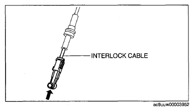
- Push the interlock cable.
 Courtesy of MAZDA MOTORS CORP.
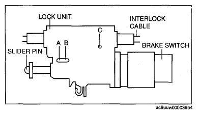
- Verify that the marking on the slider pin is positioned as shown in the illustration.
 Courtesy of MAZDA MOTORS CORP.
- Push a 1.5 mm {0.059 in}
round bar or similar into hole A by fully pushing the slider pin in.
 Courtesy of MAZDA MOTORS CORP.
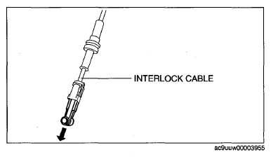
- Fully pull the end of the interlock cable.
 Courtesy of MAZDA MOTORS CORP.
- Push a 1.5 mm {0.059 in}
round bar or similar into hole B and hole C of the lock unit until it passes through.
- Disconnect the brake switch connector.
- Remove the brake switch. (See
BRAKE PEDAL REMOVAL/INSTALLATION
.)
- Install a new brake switch. (See
BRAKE PEDAL REMOVAL/INSTALLATION
.)
CAUTION:
- Do not connect the brake switch connector until the interlock cable is installed.
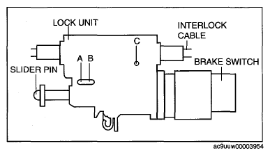 Courtesy of MAZDA MOTORS CORP.
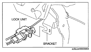
- With the slider pin pressed, slide the lock unit to fix the lock unit hook into the bracket hole securely as shown in the illustration.
CAUTION:
- Allowing the interlock cable to be bent or twisted during installation can affect the lock unit operation.
- Rotate the slider pin to release the lock and verify that it slides freely.
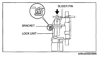 Courtesy of MAZDA MOTORS CORP.
- Pull the slider pin outward until it contacts the brake pedal stopper rubber and rotate the slider pin to lock.
- Verify that the selector lever in the P position.
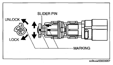 Courtesy of MAZDA MOTORS CORP.
- Install the interlock cable end to the cam pin on the selector lever component.
- Fit the interlock cable in the U-groove in the selector lever base plate and install the clip.
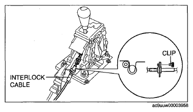 Courtesy of MAZDA MOTORS CORP.
- Press the interlock cable lock piece in until it is locked.
CAUTION:
- Applying a load to the interlock cable while pressing the lock piece in can affect the lock unit operation.
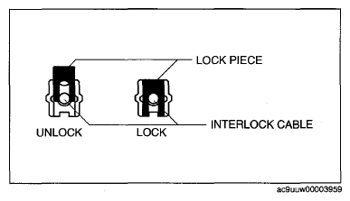 Courtesy of MAZDA MOTORS CORP.
- Remove a 1.5 mm {0.059 in}
round bar or similar from the lock unit holes A, B, and C.
- Connect the brake switch connector with the brake pedal released.
CAUTION:
- The clearance between the brake switch and the brake pedal is automatically adjusted to the correct amount when the brake switch connector is connected after the brake switch has been properly installed. If the brake switch is not properly installed or the connector is connected before installation, the clearance may be incorrect, causing a brake light malfunction. Therefore, always verify that the brake switch is properly installed before connecting the connector.
- Once the brake switch clearance has automatically been adjusted, it cannot be adjusted again. Therefore, replace the switch with a new one when replacing the power brake unit or the pedal, or performing any procedure that changes the pedal stroke.
Courtesy of MAZDA MOTORS CORP.
- Turn the ignition switch to ON position.
- Install the interlock cable to the steering lock.
- Slide the outer casing to the steering lock and insert the clip over the convex part of the outer casing.
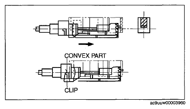 Courtesy of MAZDA MOTORS CORP.