Air Mix Control Circuit
- Remove logicon switch assembly from vehicle and connect a 12-volt battery to terminals "L" and "d". See Figure. Connect a resistance of at least 1000 ohms between terminals "Q" and "T". See Figure. Set temperature control lever to center position between maximum hot and maximum cold.
- Connect a jumper wire between terminals "V" and "U". Using a voltmeter, verify voltage between terminals "T" and "L" is approximately 12 volts. If not, replace logicon switch assembly. Verify voltage between terminals "Q" and "L" is less than one volt. If not, replace logicon switch assembly.
- Connect a resistance of at least 1000 ohms between terminals "Q" and "T". See Figure. Connect a jumper wire between terminals "V" and "S". Set temperature control lever to center position between maximum hot and maximum cold.
- Using a voltmeter, verify voltage between terminals "Q" and "L" is approximately 12 volts. If not, replace logicon switch assembly. Verify voltage between terminals "T" and "L" is less than one volt. If not, replace logicon switch assembly.
- Connect a resistance of at least 1000 ohms between terminals "Q" and "T". See Fig 1. Set temperature control lever to maximum hot position and verify voltage at terminal "Q" is higher than voltage at terminal "T". If not, replace logicon switch assembly.
- Connect a resistance of at least 1000 ohms between terminal "Q" and "T". See Fig 2. Set temperature control lever to maximum cold and verify voltage at terminal "T" is higher than that at terminal "Q". If not, replace logicon switch assembly.
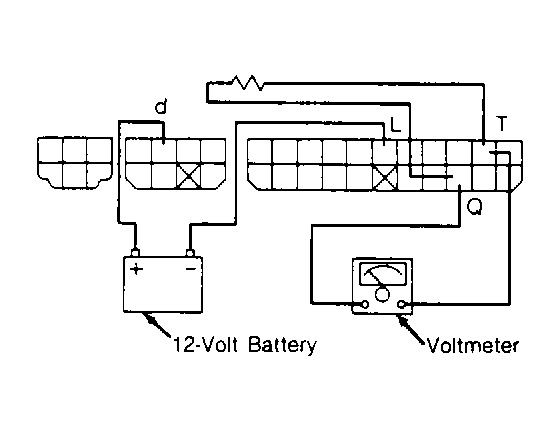 Courtesy of MAZDA MOTORS CORP.
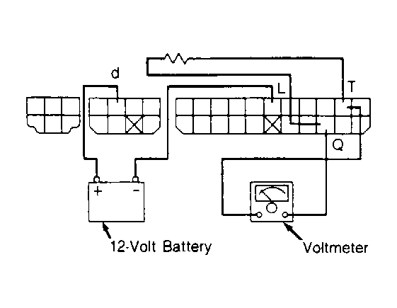 Courtesy of MAZDA MOTORS CORP.