Test 4, Actuator Circuit
- Disconnect actuator connector. See Figure. Check for continuity between ground and wiring harness side of actuator connector White/Black wire terminal. If continuity is exists, go to next step. If continuity does not exist, repair faulty ground, or locate and repair open in wiring harness between ground and actuator connector.
- Check actuator. See ACTUATOR TEST under COMPONENT TESTING. Replace actuator as necessary and recheck system operation. If actuator is okay, check if stoplight is adjusted properly. See STOPLIGHT SWITCH ADJUSTMENT under ADJUSTMENTS. Adjust switch as necessary. If switch is adjusted properly, go to next step.
- Reconnect actuator connector. Disconnect stoplight switch 4-pin connector. Measure resistance between ground and wiring harness side of stoplight switch connector terminal No. 4 (Red/Green wire). If resistance is about 39 ohms, go to next step. If resistance is not about 39 ohms, locate and repair open or short in wiring harness between stoplight switch and actuator.
- Check stoplight switch. See STOPLIGHT SWITCH TEST under COMPONENT TESTING. Replace switch as necessary and recheck system operation. If stoplight switch is okay, reconnect stoplight switch connector. Disconnect CC ECU connector. See Figure. Measure resistance between ground and CC ECU terminal No. 10. See Fig 1. If resistance is about 39 ohms, go to next step. If resistance is not about 39 ohms, locate and repair open or short in wiring harness between CC ECU connector terminal No. 10 and actuator.
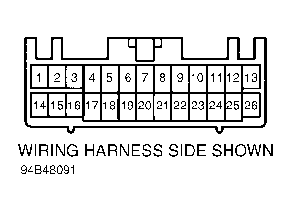 Courtesy of © TOYOTA, LICENSE AGREEMENT TMS1002
- Check for continuity between ground and CC ECU connector terminal No. 12. See Fig 1. If continuity does not exist, go to next step. If continuity exists, locate and repair short in wiring harness between CC ECU connector terminal No. 12 and actuator.
- Check for continuity between ground and CC ECU connector terminal No. 11. If continuity does not exist, go to next step. If continuity exists, locate and repair short in wiring harness between CC ECU connector terminal No. 11 and actuator.
- With actuator arm in any position other than full open or full closed position, check for continuity between CC ECU connector terminals No. 11 and 12. If continuity exists, go to next step. If continuity does not exist, locate and repair open in wiring harness between CC ECU connector and actuator.
- Check for continuity between ground and CC ECU connector terminal No. 24. If continuity does not exist, go to next step. If continuity exists, locate and repair short in wiring harness between CC ECU connector terminal No. 24 and actuator.
- Measure resistance between CC ECU connector terminals No. 24 and 26. If resistance is about 2000 ohms, go to next step. If resistance is not about 2000 ohms, locate and repair open in wiring harness between CC ECU connector terminal No. 24 or 26 and actuator.
- Connect ohmmeter leads between CC ECU connector terminals No. 25 and 26. Move actuator arm and observe ohmmeter. If resistance does not change, locate and repair open or short in wiring harness between CC ECU connector terminal No. 25 and actuator. If resistance changes, replace CC ECU and recheck system operation.