Relay Circuit
- Remove instrument panel safety pad below steering column. Turn ignition on. Continuity should exist between wiper relay connector terminal No. 15 and ground. See Fig 1. If continuity does not exist, trace and repair problem circuit.
- Turn ignition on. Measure voltage between wiper relay connector terminals No. 1 and 15. Battery voltage should not be present with wiper switch in OFF or HI position. Battery voltage should be present with wiper switch in LO or INT position. If voltage is not as specified, trace and repair problem circuit.
- Measure voltage between wiper relay connector terminals No. 2 and 15. Battery voltage should not be present with wiper switch in OFF, INT or LO position. Battery voltage should be present with wiper switch in HI position. If voltage is not as specified, trace and repair problem circuit.
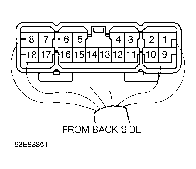 Courtesy of © TOYOTA, LICENSE AGREEMENT TMS1002
- Measure voltage between wiper relay connector terminals No. 3 and 15. Battery voltage should be present with wiper switch in OFF, INT or LO position. No voltage should be present with wiper switch in HI position. If voltage is not as specified, trace and repair problem circuit.
- Measure voltage between wiper relay connector terminals No. 4 and 15. No voltage should be present with wiper switch in OFF position. Battery voltage should be present with wiper switch in LO position. If voltage is not as specified, trace and repair problem circuit.
- Measure voltage between wiper relay connector terminals No. 5 and 15. See Fig 1. Battery voltage should be present with wiper switch in any operating position. If voltage is not as specified, trace and repair problem circuit.
- Measure voltage between wiper relay connector terminals No. 6 and 15. No voltage should be present with wiper switch in HI or OFF position. Voltage should be more than 9 volts with wiper switch to INT or LO position. If voltage is not as specified, trace and repair problem circuit.
- Measure voltage between wiper relay connector terminals No. 7 and 15. Battery voltage should be present with wiper switch in any operating position. Measure voltage between wiper relay connector terminals No. 8 and 15. Battery voltage should be present. If voltage is not as specified, trace and repair problem circuit.
- Measure voltage between wiper relay connector terminals No. 9 and 15. Battery voltage should be present with wiper switch in OFF or HI position. No voltage should be present with wiper switch in INT or LO position. If voltage is not as specified, trace and repair problem circuit.
- Measure voltage between wiper relay connector terminals No. 10 and 15. See Fig 1. Battery voltage should be present with wiper switch in OFF, LO and HI position. No voltage should be present with wiper switch in INT position. If voltage is not as specified, trace and repair problem circuit.
- Measure voltage between wiper relay connector terminals No. 11 and 15. See Fig 1. Battery voltage should be present with washer switch in OFF position. Measure voltage between ground and wiper relay connector terminal No. 11. No voltage should be present with washer switch in ON position. If voltage is not as specified, trace and repair problem circuit.
- Measure voltage between wiper relay connector terminals No. 13 and 15. Battery voltage should be present with parking position in FULL position. No voltage should be present with parking position in SEMI position. If voltage is present, trace and repair short to voltage in circuit.
- Measure voltage between wiper relay connector terminals No. 15 and 16. See Fig 1. No voltage should be present with wiper switch in OFF or HI position. Voltage should be more than 9 volts with wiper switch in INT or LO position. If voltage is not as specified, trace and repair problem circuit.
- Measure voltage between wiper relay connector terminals No. 15 and 17. No battery voltage should be present. If voltage is not as specified, trace and repair problem circuit.
- With wiper switch in slow intermittent position, resistance between wiper relay connector terminals No. 14 and 18 should be 50,000 ohms. With wiper switch in fast intermittent position, resistance between these terminals should be less than 10 ohms. If resistance is incorrect, replace wiper/washer switch.