Tilt Wheel: Reassembly
- Coat all friction surfaces with multi-purpose grease before reassembly. Mount shift bowl on column. Place shift tube spring, wave washer, and retainer plate in shift bowl.
- Install shift tube through lower end of column. Make sure tube spline is aligned with shift bowl keyway. Place shift tube installed tools (J-23073-2 and J-23073-4) in shift tube. Make sure spring loaded lower foot of tool is engaged with shift tube inner shoulder and tool guide is seated in shift tube. See Fig 1.
- Tighten tool spring tension nut until snug. Place installer tools (J-23073-3 and J-23073-4) over puller stud. Tighten tool nut (J-23073-2) and pull tube into place in shift bowl. Remove shift tube installer tools. See Fig 2.
- Install shift tube thrust washer and retainer plate snap ring. Install lower bearing adapter, making sure notched end of adapter faces lower end of column. Install lower bearing in column. Make sure metal face of bearing faces lower end of column. Install lower bearing retainer and retainer spring clip.
- Install shift gate in support and install shift gate attaching screws. Install support in shift bowl. Make sure "V notch in support is aligned with notch in column. Install support to shift bowl screws.
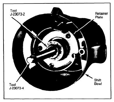 Courtesy of CHRYSLER GROUP, LLC
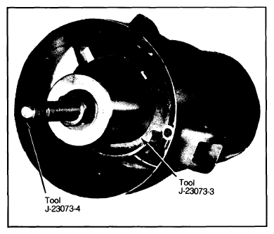 Courtesy of CHRYSLER GROUP, LLC
- Assemble upper and lower steering shaft at flexible joint. Install steering shaft through upper end of column. Install ball bearings in housing if removed. Make sure there are 14 balls in each bearing.
- Install tilt release handle. Insert ignition switch remote rod between shift bowl and column and into guide channel in left side of support. Engage lock rack in remote rod. Guide housing over steering shaft and lock rack, making sure lock shoes align with teeth in support.
- Align housing and support pivot pin holes and drive in pivot pins using a soft faced mallet. Install lock shoe spring, tilt bumpers and lock pin in housing. Install sector shaft in housing and lock sector in on shaft. Large block tooth of sector must engage large slot in rack.
- Install sector shaft snap ring. Hook lock sector tension spring on lock bolt. Engage spring with sector and install spring retaining screw. Place housing in full upward tilt position. Install tilt spring and guide in housing.
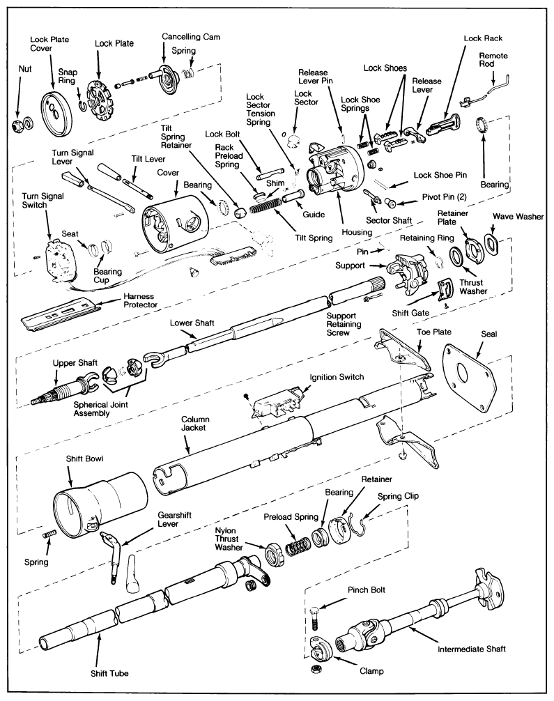 Courtesy of CHRYSLER GROUP, LLC
- Push tilt spring retainer into housing 3/16" and rotate retainer 1/8 turn clockwise to secure retainer tabs in housing lugs. Place housing in center tilt position. Remove tilt release handle. Install cover on housing and install retaining screws.
- Insert shift quadrant light wire up through housing and between shift bowl and column jacket. Install shift quadrant mounting bracket and connect light socket. Hook base of shift quadrant over tabs on left side of quadrant and place in position.
- Install quadrant pointer in shift bowl and engage in quadrant. Install quadrant retainer clip with flat side of clip facing downward. Install tilt release handle. Place directional signal switch and harness in column. Guide harness between cover and column.
- On vehicles without Cruise Command, install directional signal lever. On vehicles with Cruise Command, install directional signal lever and Cruise Command switch assembly. Use string taped to connector during disassembly to install connector.
- Remove tape and string from connector. Connect four wires to switch terminal. Install and tighten lever screw. Place directional signal switch harness in plastic protector. Align directional signal switch in cover. Install and tighten retaining screws.
NOTE:
Make sure switch actuating lever pivot is correctly aligned and seated in housing pivot boss before installing switch attaching screws.
- Install bearing race, bearing race seat, preload spring, and cancelling cam on steering shaft. Align lock plate splines with steering shaft splines. Install lock plate. Make sure cancelling cam shaft protrudes through hole in lock plate.
- Install new steering shaft snap ring on lock plate compressor tool (J-23653 for American threaded steering shaft nut, J-23653-4 for metric threaded nut). Position tool on steering shaft. Compress lock plate with tool. Install snap ring in groove in steering shaft. Remove tool.
- Place gearshift lever in shift bowl. Guide gearshift lever over lock sector tension spring and into bowl. Align retaining pin holes with a punch. Drive retaining pin into position using a soft faced hammer.
- Insert ignition key into lock cylinder. Hold lock cylinder and turn key clockwise to stop. Align cylinder locking lug with keyway in cover and insert cylinder in cover. Push cylinder against lock sector. Rotate cylinder counterclockwise until it engages sector. Push cylinder inward until retainer tab snaps into place.
- Install steering column as previously outlined. Install steering wheel. Adjust gearshift linkage, and neutral safety and back-up lamp switch.
- Coat all friction surfaces with multipurpose grease before reassembly. Install bearing assembly, bearing retainer and snap ring in lower end of column.
- Install key release lever spring on lever and install assembled lever and spring in shroud. Align and install shroud on column jacket.
- Install retainer plate by tipping plate to 12 o'clock position and sliding it under jacket opening. Align column jacket "V" notch with "V" on support and install support in column. Press key release lever down while pressing support into place.
- Install support attaching screws finger tight then tighten alternately to specifications. Install remote rod in support by guiding rod through upper end of shroud and into rod slot in support.
- Install steering shaft in column. Install bearings (if removed). Install lock shoe, springs and lock shoe pin in housing. Use 0.18" (4.6mm) diameter rod to align lock shoes and pin.
- Install release lever, lever spring and lever pin in housing. Insert wedges between housing and lever to relieve spring tension. Install sector shaft in housing. Lightly tap shaft into housing using punch.
- Install lock sector on shaft. Lightly tap sector onto shaft until shaft snap ring groove is exposed. Install sector snap ring. Install lock bolt in housing and engage bolt in lock sector cam surface.
- Install lock rack, rack preload spring and shim in housing. Square block tooth of rack must engage square block tooth of sector. Install lock spring and retaining screw.
- Align and install assembled housing on support. Hold lock shoes in disengaged position to ease housing installation. Align pivot pin holes in housing and support and install pivot pins. When started in holes, seal pins fully using a hammer and punch. Press housing downward when first installing pins to avoid damage to pin holes.
- Insert tilt lever in housing and place housing in full upward tilt position. Lubricate tilt guide and spring and install tilt spring on guide. Insert assembled tilt spring and guide in housing and install guide retainer on spring.
- Install tilt lever shield. Remove tilt lever. Install cover on housing. Install turn signal switch. Guide switch harness and connector through column and into housing. Do not install switch attaching screws at this time.
- Install hazard warning switch knob in turn signal switch and align and install switch attaching screws. Make sure turn signal switch is properly aligned before tightening screws. Pull out on hazard warning knob.
- Install upper bearing race and seat in housing. Install upper bearing preload spring, cancelling cam and lock plate.
- Install new steering shaft snap ring on compressor tool (J-23653 for American threaded steering shaft nut, J-23653-4 for metric threaded nut) and install tool on steering shaft. Compress lock plate and seat snap ring. Remove tool.
- Install tilt and turn signal levers. Install shift lever and retaining pin. Install ignition lock cylinder. Hold cylinder sleeve, turn knob clockwise against stop, align cylinder tab with housing keyway and install cylinder in housing. Turn cylinder knob counterclockwise until cylinder mates with lock sector and push cylinder in until retainer snaps into place.
- Insert key in cylinder and turn cylinder to "OFF" position. Install ignition switch. Move switch to "ACC position then back off two clicks to "OFF" position. Remote rod hole should almost be at center.
- Insert remote rod into hole and install switch on column jacket. Move switch down to eliminate lash and tighten attaching screws. Position switch harness protectors over harness and snap into place.
- Install lock plate cover. Install steering wheel. Install column in vehicle.
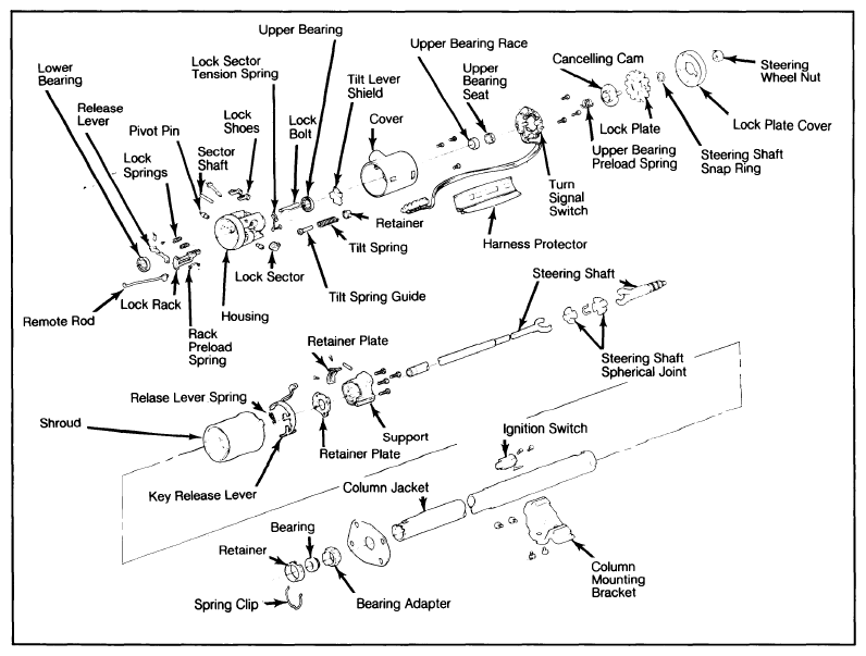 Courtesy of CHRYSLER GROUP, LLC
TIGHTENING SPECIFICATIONS
| Application |
Ft. Lbs. (N.m) |
| Column Mounting Bracket Bolt |
20 (27) |
| Intermediate Shaft Pinch Bolt |
45(61) |
| Mounting Bracket-to-instrument Panel Bolts |
20 (27) |
| Steering Wheel Nut |
30(41) |
| Toe Plate Bolts |
10 (14) |
| Application |
INCH Lbs. (N.m) |
| Cover Screws |
60 (7) |
| Housing Screws |
60 (7) |
| Ignition Switch Mounting Screws |
35 (4) |
| Lock Sector Tension Spring Screw |
35 (4) |
| Shroud Screws (Man. Trans.) |
18 (2) |
| Support Screws (Tilt Column) |
60 (7) |
| Tilt Lever Screw |
35 (4) |
| Turn Signal Lever Screw |
35 (4) |
| Turn Signal Switch Screws |
35 (4) |