Cruise Control MODUL
Disconnect cruise control module connector. Perform all circuit tests at cruise control module wiring harness connector. SeeFig 1
. Ensure ignition and cruise control main switch are on. Unless told otherwise, check circuit between specified terminal and ground. See CRUISE CONTROL MODULE HARNESS CONNECTOR TERMINAL
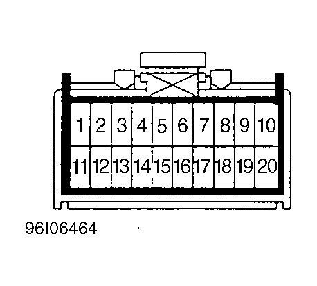 Courtesy of ISUZU MOTOR CO.
 CRUISE CONTROL MODULE HARNESS CONNECTOR TERMINAL
| Between |
Circuit |
Test Condition |
Specification |
| 3 & Gnd |
Cruise Indicator Light |
Ignition & Main Switch On |
12 Volts |
| 4 & Gnd |
Clutch Switch (M/T) |
Pedal Released |
0 Volts |
| 4 & Gnd |
Clutch Switch (M/T) |
Clutch Depressed |
12 Volts |
| 4 & Gnd |
Mode Switch (A/T) |
P R & N |
0 Volts |
| 4 & Gnd |
Mode Switch (A/T) |
D 3 2 & 1 |
12 Volts |
| 5 & Gnd |
Vent Valve |
See CRUISE CONTROL ACTUATOR Test |
62-72 Ohms |
| 6 & Gnd |
Gnd |
N/A |
Continuity To Ground |
| 7 & Gnd |
Vacuum Pump |
See CRUISE CONTROL ACTUATOR Test |
2 Amps Max. |
| 9 & Gnd |
Resume Switch |
Resume & Main Switch On |
12 Volts |
| 10 & Gnd |
Set Switch |
Set & Main Switch On |
12 Volts |
| 14 & Gnd |
Safety Valve |
See CRUISE CONTROL ACTUATOR Test |
62-72 Ohms |
| 15 & Gnd |
Battery + |
Ignition & Main Switch On |
12 Volts |
| 16 & Gnd |
Brakelight Switch |
Pedal Depressed |
0 Volts |
| 16 & Gnd |
Brakelight Switch |
Pedal Released |
12 Volts |
| 19 & Gnd |
VSS |
N/A |
Voltage |
| 20 & Gnd |
Brakelight Switch |
Pedal Released/Depressed |
0 Volts/12 Volts |