Procedure "B"
- Start engine and warm to normal operating temperature. Turn ignition off. Connect a vacuum gauge with a "T" to hose between AP sensor and MAP/BARO solenoid. See Figure and Fig 1
. While monitoring vacuum gauge, start engine and let it idle. Vacuum should not exist for 5 seconds. Vacuum should exist after 5 seconds. If vacuum is as specified, go to step 3. If vacuum is not as specified, go to next step.
- Check vacuum supply to MAP/BARO solenoid. Repair as necessary and retest. If vacuum supply is okay, remove MAP/BARO solenoid. Using jumper wires, apply battery voltage between MAP/BARO solenoid terminals. See Fig 2. Air should flow between ports "A" and "B". Air should not flow between ports "A" and "C". Remove jumper wires. Air should flow between ports "A" and "C". Air should not flow between ports "A" and "B". MAP/BARO solenoid should switch in less than one second. Replace MAP/BARO solenoid, if operation is not as specified. Retest system. If operation is as specified, check intake system for air leaks. Repair as necessary and retest system.
- Turn ignition off. Inspect vacuum hose between AP sensor and MAP/BARO solenoid for clogging or leaks. Repair as necessary and retest system. If vacuum hose is okay, go to next step.
- Remove AP sensor from its bracket and disconnect vacuum hose. Turn ignition on. Measure voltage between engine ground and ECM terminal No. 64 by backprobing. See Figure. Voltage should be 3.2-4.8 volts. Using a hand vacuum pump, apply 7.87 in. Hg of vacuum to AP sensor. Voltage should be 1.0-1.4 volts less than voltage measured with no vacuum applied. Voltage should decrease as vacuum is applied. See Figure. If voltage is as specified, go to next step. If voltage is not as specified, replace AP sensor and retest system.
- No problem is indicated at this time. Problem may be intermittent. See INTERMITTENTS in TROUBLE SHOOTING - NO CODES article.
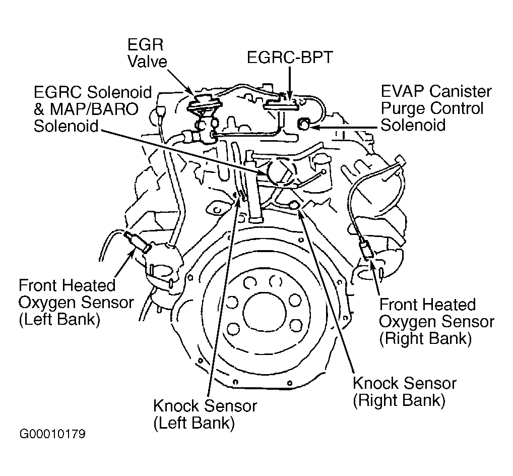 Courtesy of NISSAN MOTOR CO., U.S.A.
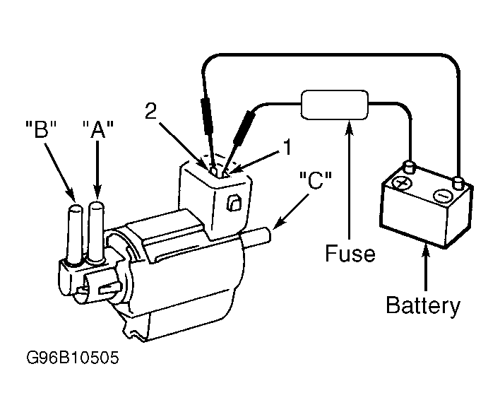 Courtesy of NISSAN MOTOR CO., U.S.A.