Engine Assembly
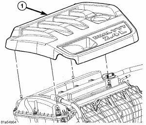 Courtesy of CHRYSLER LLC
- Remove engine cover (1).
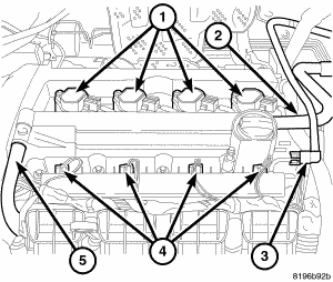 Courtesy of CHRYSLER LLC
- Perform fuel pressure release procedure, then disconnect and remove fuel line (3). Refer to STANDARD PROCEDURE
.
- Remove make-up air hose (2).
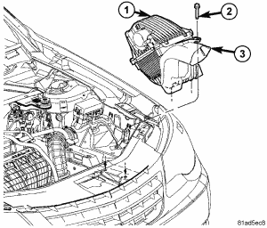 Courtesy of CHRYSLER LLC
- Remove air cleaner housing assembly (1). See REMOVAL .
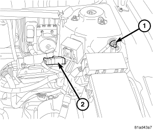 Courtesy of CHRYSLER LLC
- Disconnect negative battery cable (1).
- Discharge air conditioning system, if equipped. Refer to HEATING & AIR CONDITIONING - SERVICE INFORMATION
.
- Drain cooling system. Refer to COOLING
.
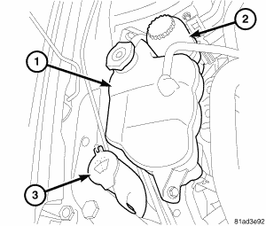 Courtesy of CHRYSLER LLC
- Remove coolant reservoir (1).
- Remove power steering reservoir (2).
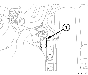 Courtesy of CHRYSLER LLC
- Remove power steering line support at engine mount (1).
- Remove power steering pump and set aside.
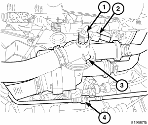 Courtesy of CHRYSLER LLC
- Remove coolant hoses from coolant adapter (3).
- Disconnect coolant temperature sensor connector (1) and capacitor connector (2).
Courtesy of CHRYSLER LLC
- Disconnect coils (1), injectors (4), cam sensors, oil temperature sensor, and oil control valve electrical connectors and reposition harness.
- Remove PCV hose (5) from valve cover.
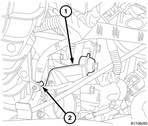 Courtesy of CHRYSLER LLC
- Remove harness from intake (2).
- Remove throttle body support bracket (1).
- Remove vacuum lines from throttle body and intake manifold.
- Disconnect electronic throttle control and manifold flow control valve electrical connectors.
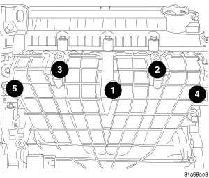 Courtesy of CHRYSLER LLC
- Remove dipstick.
- Remove intake bolts and remove intake.
- Disconnect coolant temperature sensor at block, knock sensor, oil pressure sensor, generator, starter, block heater (if equipped), A/C compressor (if equipped), and block ground.
- Remove accessory drive belt.
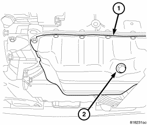 Courtesy of CHRYSLER LLC
- Raise vehicle.
- Remove front splash shield.
- Drain oil (2).
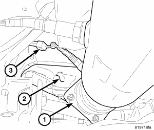 Courtesy of CHRYSLER LLC
- Remove exhaust pipe to exhaust manifold bolts (1).
- Disconnect oxygen sensor connector (3).
- Remove exhaust manifold heat shield (2).
- Remove exhaust manifold.
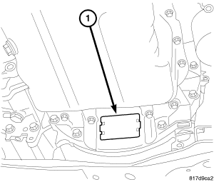 Courtesy of CHRYSLER LLC
- Remove inspection cover (1) and mark torque converter to flywheel.
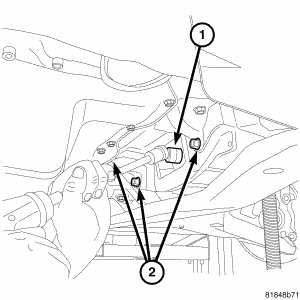 Courtesy of CHRYSLER LLC
- On vehicles equipped with an automatic transaxle, remove torque converter bolts (1).
- On vehicles equipped with an manual transaxle, remove modular clutch bolts (1).
- Remove lower bellhousing bolts (2).
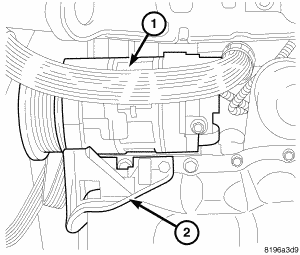 Courtesy of CHRYSLER LLC
- Remove A/C compressor (1) from engine and set aside.
- Remove generator and lower idler pulley.
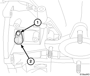 Courtesy of CHRYSLER LLC
- Disconnect CKP sensor (2) electrical connector.
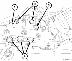 Courtesy of CHRYSLER LLC
- Remove right engine mount bracket retaining bolts (4).
- Remove power steering hose hold down (3).
- Remove retaining nuts (2) and position mount bracket (1) aside.
 Courtesy of CHRYSLER LLC
- Remove intake oil control valve to prevent damage.
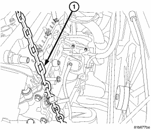
- Install engine lift chain to rear lift bracket and bolt to cylinder head (1) in the front.
- Hoist engine from vehicle.
- Separate engine and transmission.