Electrical Test
- Turn ignition and speed control main switch to on position. Disconnect speed control servo 4-pin connector. Using a DVOM, measure voltage between ground and servo harness connector terminal No. 3 (Blue/White wire). See Fig 1. If battery voltage exists, go to next step. If battery voltage does not exist, check power supply circuit. See WIRING DIAGRAMS .
- Connect jumper wire between servo harness connector terminal No. 3 (Blue/White wire) and servo connector terminal No. 3. Using a DVOM, check for voltage at remaining 3 servo connector terminals. If voltage is present at all 3 remaining servo connector terminals, go to next step. If voltage is not present at all 3 remaining servo connector terminals, replace speed control servo. See SPEED CONTROL SERVO under REMOVAL & INSTALLATION.
- Turn ignition off and remove jumper wire. Using a DVOM, check for continuity between ground and servo harness connector terminal No. 4 (Black wire). See Fig 1. Continuity should exist. If continuity does not exist, repair open in speed control servo ground circuit. See WIRING DIAGRAMS .
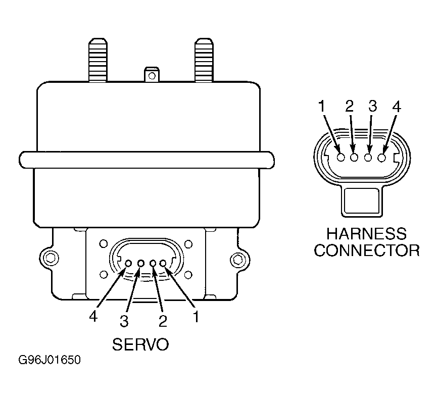 Courtesy of CHRYSLER CORP.