Control Switch/Timer Relay Test
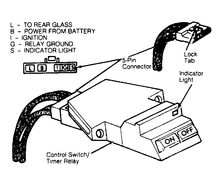
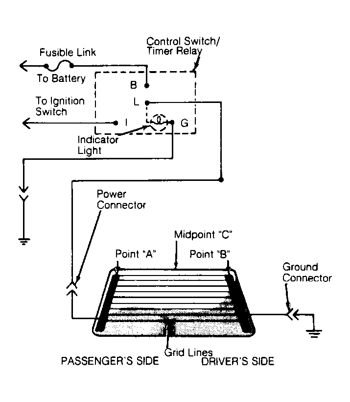
- Remove control switch/timer relay from instrument panel with wiring still connected. See appropriate INSTRUMENT PANEL article in INSTRUMENT PANEL section. Turn ignition on. Using a DC voltmeter, check for voltage at terminals "B", "I" and "L". See Fig 1
and Fig 2
. Both "B" and "I" should have 10-14 volts. Terminal "L" should have zero volts.
 Courtesy of CHRYSLER MOTORS.
 Courtesy of CHRYSLER MOTORS.
- If terminals "B" and "I" show no voltage, check circuit for defective wiring, blown fusible link, open circuit breaker or loose connection at bulkhead connector. If terminal "L" shows voltage, move control switch to the OFF position. If voltage at terminal "L" is still present or indicator light remains on, replace control switch/timer relay.
- If control switch/timer relay voltages are correct, move control switch to the ON position. Voltage should be present at terminal "L" for about 10 minutes and indicator light should be on. If light is off or no voltage is present at terminal "L", replace control switch/timer relay.